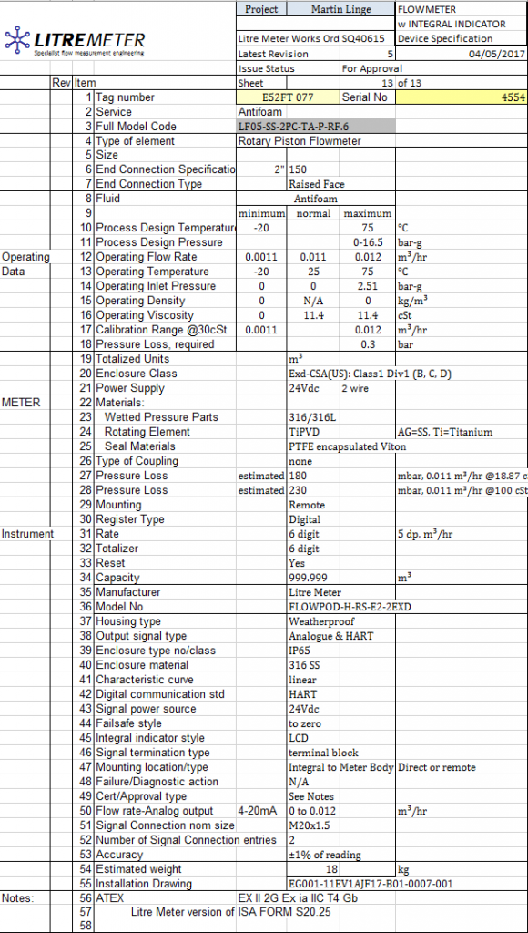
A typical datasheet relating to a flowmeter is given as below – this one is based on a NORSOK format:
This one is for the same meter but based on an ISA format (a version used by Litre Meter which uses S20.25 as it’s base):
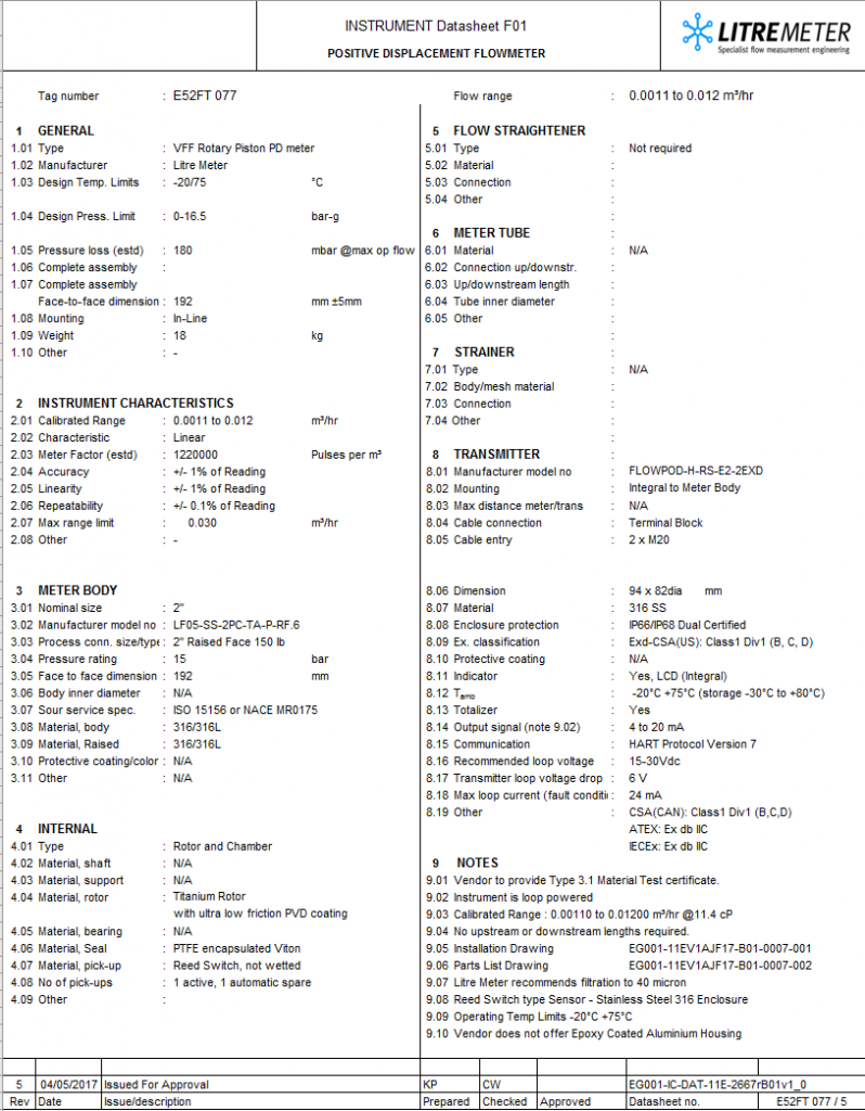
Norsok:
This is an approximate layout, typified by NORSOK.
1 General
1.01 Type – a description of the flowmeter, by trade name and basic principle
1.02 Manufacturer – manufacturer’s name.
1.03 Design Temperature Limits – maximum and minimum design temperatures in suitable temperature units (°C)
1.04 Design Pressure Limits – maximum and minimum design pressures in suitable pressure units (bar gauge)
1.05 Estimated Pressure Loss – pressure drop at a specific flow such as maximum in suitable units (millibar)
1.07 Face to face dimension – complete assembly length in millimetres, with a tolerance
1.08 Mounting – type of mounting, in this case, In-Line but could be insertion, clamp-on etc.
1.09 Weight – dry, without fluids – in kilogrammes
2 Instrument Characteristics
2.01 Calibrated Range – flow rate range that the unit will be calibrated over – and units
2.02 Characteristic – an appreciation that not all meters are necessarily linear – some are non-linear such as orifice plates where the pressure drop is related to the flow rate by a square law, in this case linear – and linearised.
2.03 Meter factor – an estimated value of the number of pulses per litre – or other volume or mass unit
2.04 Accuracy – with percentage bounds and either proportional to the actual reading or FSD (Full Scale Deflection)
2.05 Linearity – with percentage bounds and either proportional to the actual reading or FSD (Full Scale Deflection)
2.06 Repeatability – with percentage bounds and proportional to the actual reading
2.07 Max Range limit – not necessarily the same as the maximum calibrated flow – describes the capabilities of the flowmeter
3 Meter Body
3.01 Nominal Size – normally relating the meter body size to the pipe size
3.02 Manufacturer model number – to precisely define the scope of supply
3.03 Process connection size and type – Size and flange or thread type, for example
3.04 Pressure rating – the rating of the flowmeter body in comparable units to 1.04
3.05 Face to face dimension – will match 1.07 in most cases
3.06 Body inner diameter – where appropriate
3.07 Sour service specification – nominated when appropriate – ISO or NACE in this example
3.08 Material, body – A specification for the material of the flowmeter body i.e. the main part of the meter
3.09 Material, Raised –
3.10 Protective coating/color
3.11 Other
4 INTERNAL
4.01 Type – such as rotor and chamber or another description of the flowmeter internals and principle
4.02 Material, shaft – if any
4.03 Material, support – if any – this might refer to a turbine flowmeter part
4.04 Material, rotor
4.05 Material, bearing – if any, may include material and type
4.06 Material, Seal – not just the materials but may include seal type
4.07 Material, pick-up – i.e. sensor material, wetted, or not
4.08 No of pick-ups
4.09 Other
5 FLOW STRAIGHTENER
5.01 Type
5.02 Material
5.03 Connection
5.04 Other
6 METER TUBE
6.01 Material
6.02 Connection up/downstr.
6.03 Up/downstream length
6.04 Tube inner diameter
6.05 Other
7 STRAINER
7.01 Type
7.02 Body/mesh material
7.03 Connection
7.04 Other
8 TRANSMITTER
8.01 Manufacturer model no
8.02 Mounting
8.03 Max distance meter/trans
8.04 Cable connection
8.05 Cable entry
8.06 Dimension
8.07 Material
8.08 Enclosure protection
8.09 Ex. classification
8.10 Protective coating
8.11 Indicator
8.12 Tamb
8.13 Totalizer
8.14 Output signal (note 9.02)
8.15 Communication
8.16 Recommended loop voltage
8.17 Transmitter loop voltage drop
8.18 Max loop current (fault condition)
8.19 Other – in this case describes more of the hazardous area ratings and standards – CSA, IECEx and ATEX